 Silicone Manufacturer for Custom Silicone Products
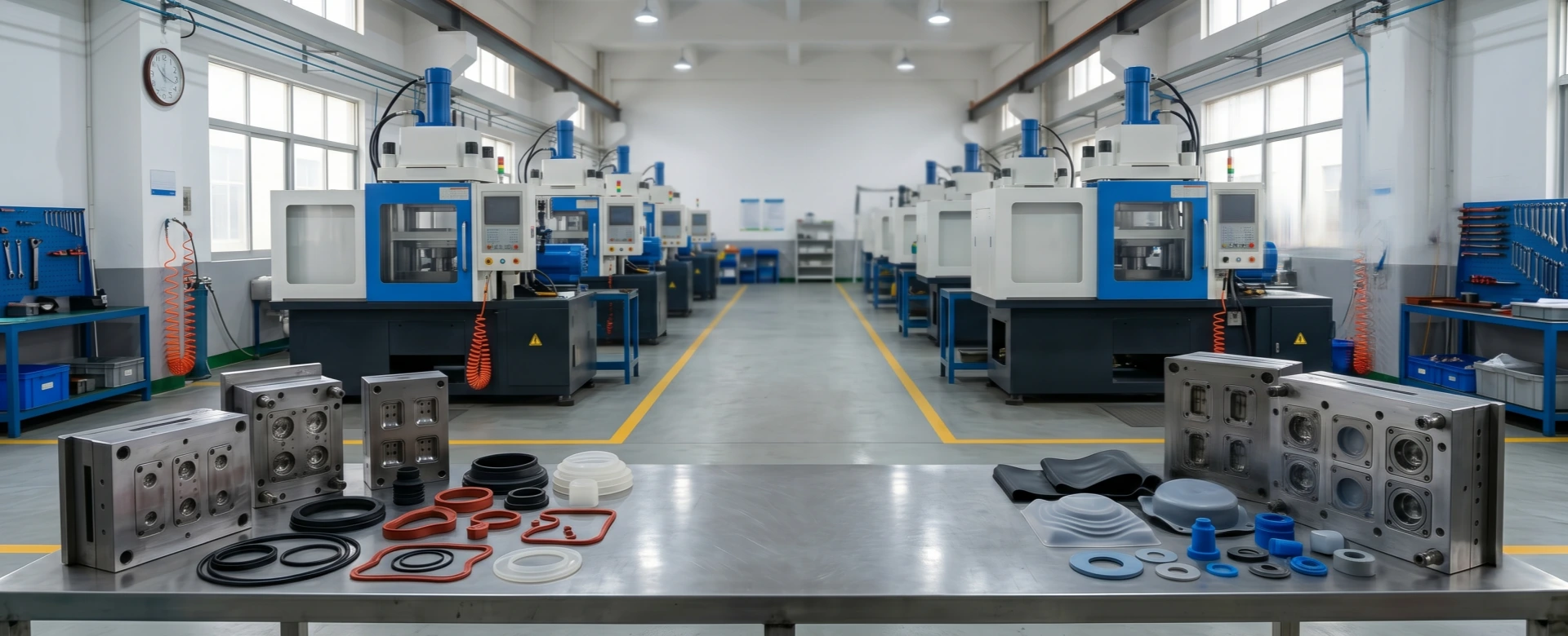
Vacuum Compression Molding: Eliminating Internal Voids and Trapped Air in Complex Parts
In high-precision silicone elastomer molding and industrial volume manufacturing, hardware developers and quality directors frequently face a severe, non-negotiable processing flaw: internal micro-voids and trapped atmospheric air bubbles. During standard compression molding sequences, when raw solid unvulcanized silicone preforms are compressed under heavy clamp press tonnage, ambient atmospheric air gets sealed inside deep mold pockets, rib configurations, or thick cross-sectional features.
Failing to eliminate these hidden internal cavities during the vulcanization phase leads to premature dynamic cracking, localized mechanical failures, and catastrophic field product recalls.
For industrial components, these internal voids act as high-stress concentration points. In high-voltage electrical insulation applications, trapped air pockets cause catastrophic localized dielectric tracking and premature breakdown. This engineering portfolio details the integration of advanced Vacuum Compression Molding setups to thoroughly evacuate atmospheric air before vulcanization, ensuring zero-void manufacturing stability for complex components.
1. Kinetic Mechanism: Traditional Bump-Venting vs. Active Vacuum Evacuation
Traditional compression molding setups rely almost exclusively on physical “bump-venting” cycles to expel entrained air from the tool cavities. In a standard bumping sequence, the hydraulic press closes to compress the unvulcanized rubber compound, re-opens slightly to let trapped gas escape to the atmosphere, and quickly bumps closed again to finish curing. While this approach works for basic flat shapes, it exhibits high failure rates when processing thick walls or intricate multi-cavity tools.
Because unvulcanized silicone rubber cross-links quickly under high cavity temperatures, its surface viscosity escalates rapidly during initial compression.
This rapid skin-forming effect traps pockets of ambient air deep within deep cross-sections or complex internal corners. The trapped gas cannot escape through the curing polymer shell, resulting in permanent structural voids.
Active vacuum compression systems completely bypass this limitation by enclosing the entire mold base inside a sealed vacuum shroud. High-displacement vacuum pumps exhaust the chamber down beneath 5 mbar before the tool plates touch, ensuring no air remains to be trapped as the compound expands.
2. Dielectric and Structural Failures Caused by Micro-Voids
Eliminating internal micro-voids is critical for parts operating under high structural or electrical stress profiles:
- Electrical Insulation Degradation: In high-voltage cable connectors, transformer bushings, and utility insulators, silicone serves as the primary dielectric barrier. Air features a significantly lower dielectric breakdown threshold compared to cured silicone (3 kV/mm versus 20 kV/mm). Under active high-voltage fields, the air inside a micro-void ionizes prematurely, triggering partial discharge (PD) micro-arcs. This continuous localized plasma bombardment degrades surrounding siloxane chains, causing tracking paths and catastrophic insulation failure.
- Dynamic Fatigue Rupture: For components subject to high-frequency pressure cycles or mechanical movement—such as industrial pump diaphragms, automotive turbo hoses, or heavy-duty bellows—internal air bubbles act as severe stress raisers. Under mechanical strain, micro-cracks form at these hidden void boundaries and propagate outward, leading to unexpected premature component tearing.
3. DFM Frameworks for Vacuum-Assisted Hard Tooling
To successfully leverage vacuum compression molding systems for mass production runs, product layout blueprints must follow specific tool design rules during the initial Design for Manufacturing (DFM) assessment.
First, the mold base split-lines must incorporate a specialized outer high-temperature silicone O-ring gasket track to seal the vacuum envelope before plate closure. This perimeter seal must sit far enough from the primary part cavities to prevent flash contamination during long production cycles.
Second, core pins, deep rib walls, and ejector pin channels require deliberate clearance offsets (typically 0.03mm to 0.05mm) to function as internal vacuum exhaustion paths.
These micro-channels allow vacuum extraction systems to pull residual air from deep within the tool cavities without allowing unvulcanized rubber to bleed through, maintaining tight component tolerances, reducing flash overhead, and keeping your parting lines down to strict RMA A2 precision classifications.
Secure Zero-Defect Component Manufacturing Integrity
Eliminate hidden micro-void vulnerabilities, maximize dynamic fatigue lifetime metrics, and secure certified partial discharge compliance standards for your industrial assemblies. Reemane delivers premium, vacuum-shroud tooling setups and comprehensive DFM model reviews for global engineering networks.
