 Silicone Manufacturer for Custom Silicone Products
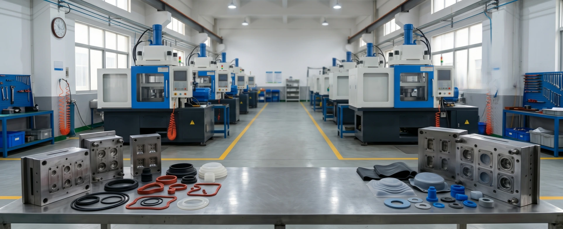
Cavity Layout Optimization: Balancing Tooling Cost with Hourly Production Output
In B2B silicone manufacturing procurement, achieving the lowest possible total piece price requires balancing upfront tooling capital expenditures (CapEx) against long-term mass production operating expenses (OpEx). Sourcing teams often default to minimizing initial tooling costs by choosing lower cavity mold layouts, such as a 2-cavity or 4-cavity setup. While this minimizes upfront tool development costs, it artificially restricts production throughput and raises piece-price variables over the life of a project.
Every compression or liquid injection mold cycle incurs a fixed machine operation and labor overhead cost per hour. If a mold produces only 2 parts per cycle instead of 16 or 32, the machine rate amortized across each finished piece increases significantly. Over large Estimated Annual Volumes (EAU), this unoptimized layout can lead to substantial hidden manufacturing costs. To prevent this, tool engineers model the total cost curve to identify the exact mathematical sweet spot where upfront tooling CapEx minimizes overall production piece prices.
1. Mathematical Modeling: Amortizing CapEx Against Piece-Price Variables
To determine the most economical tool layout, engineers calculate the Total Procurement Cost (TPC) for a given project lifecycle. The TPC combines the initial tool manufacturing cost with the piece-price cost multiplied by the total production volume ($V$):
$\text{TPC} = \text{Cost}_{\text{tooling}} + (\text{Cost}_{\text{piece}} \times V)$
The unit piece-price cost ($\text{Cost}_{\text{piece}}$) is determined by raw material mass weight alongside the machine press operating rate divided by hourly output. The hourly output is calculated by dividing the cavity count ($N$) by the press cycle time ($t_{\text{cycle}}$) in seconds:
$\text{Hourly Output} = N \times \left( \frac{3600}{t_{\text{cycle}}} \right)$
As the cavity count ($N$) expands, the hourly output scales upward linearly, which drives down the amortized machine time cost per piece. However, cutting a larger matrix of cavities raises the initial tooling cost ($\text{Cost}_{\text{tooling}}$). Plotting these variables reveals the break-even volume threshold where higher-cavity layouts become more economical than lower-cavity options.
2. Production Cost Case Study: 500,000 Unit EAU Amortization Analysis
To illustrate this economic relationship, consider a high-precision silicone gasket with a continuous press cycle time of 60 seconds, a raw material cost of $0.35 per unit, and a machine operational press rate of $45.00 per hour. Analyzing costs across 2-cavity, 8-cavity, and 32-cavity tool layouts over a 500,000-unit production run demonstrates how higher cavity counts reduce total project expenditures.
Economic Amortization Across Cavity Count Configurations
| Tool Layout Configuration | Tooling CapEx | Hourly Part Output | Base Unit Piece Price | Total Amortized Cost |
|---|---|---|---|---|
| 2-Cavity Layout | $2,200 | 120 pcs/hr | $0.725 | $364,700 |
| 8-Cavity Layout | $5,500 | 480 pcs/hr | $0.444 | $227,500 |
| 32-Cavity Cold Runner | $18,500 | 1,920 pcs/hr | $0.373 | $205,000 |
This case study demonstrates that while a 32-cavity cold-runner tool requires a higher initial investment ($18,500 vs. $2,200), its significantly higher hourly output lowers the final unit piece price. Over a 500,000-unit run, this optimization saves $159,700 compared to a 2-cavity setup, absorbing the initial tooling premium within the first few production weeks.
3. Technical Constraints: Runner Efficiency and Flash Control
Increasing cavity counts requires careful management of specific tool engineering boundaries to avoid defects like uneven material distribution or short shots. The first engineering constraint is runner system efficiency. In high-cavity layouts using traditional cold runner feeds, material paths must be perfectly balanced, ensuring the flow path length from the main sprue to each individual gate entry is completely identical. Mismatched runner balances cause outer cavities to underfill while inner positions overpack, introducing dimensional drift across parts.
The second technical limit is machine clamping tonnage. Silicone rubber features a very low viscosity during its flow phase, making it highly prone to seeping out along parting lines and forming flash if clamping pressures drop. The required closing force is calculated by multiplying the total projected surface area of all cavities and runner channels by an industry-standard pressure factor of 2.5 to 3.5 tons per square inch:
$\text{Tonnage Required} = \text{Projected Area}_{\text{total}} \times \text{Pressure Factor}$
If a 32-cavity footprint exceeds the maximum clamping tonnage of the target molding press, the mold plates will separate slightly during injection, creating thick, out-of-tolerance flash. Reemane’s tool designers resolve this by utilizing high-rigidity S136 stainless steel mold inserts, optimized plate layouts, and selective cold-runner needle valve gating to maximize cavity density while remaining safely within machine tonnage limits.
4. DFM Framework for Strategic Procurement Collaboration
To ensure consistent quality and cost control when developing high-cavity silicone molds, product blueprints should follow key design guidelines during initial CAD layout reviews:
- Symmetric Layout Balancing: Cavity arrays must be organized in geometric balances, such as 4, 8, 16, or 32-cavity patterns. Avoid odd or asymmetric configurations (like 7 or 11 cavities), which introduce severe thermal and pressure imbalances across the tool plates.
- Thermal Zone Separation: High-cavity tool blocks must incorporate independent internal cartridge heating loops to eliminate cooler perimeter zones, ensuring uniform vulcanization times across all cavities.
- Automated Part Ejection Compatibility: Parting lines, draft angles, and core slider mechanisms must be optimized for robotic pick-and-place grippers or automatic brush demolding to eliminate manual handling delays and maintain fast, predictable cycle times.
Maximize Capital Amortization on Your High-Volume Component Lines
Eliminate unoptimized cycle rate premiums, achieve balanced material distribution across multi-cavity layouts, and leverage expert rheological tool engineering to lock in the lowest total piece cost. Reemane provides full capital amortization modeling reports, verified high-cavity DFM optimization layouts, and standardized tonnage safety metrics.