 Silicone Manufacturer for Custom Silicone Products
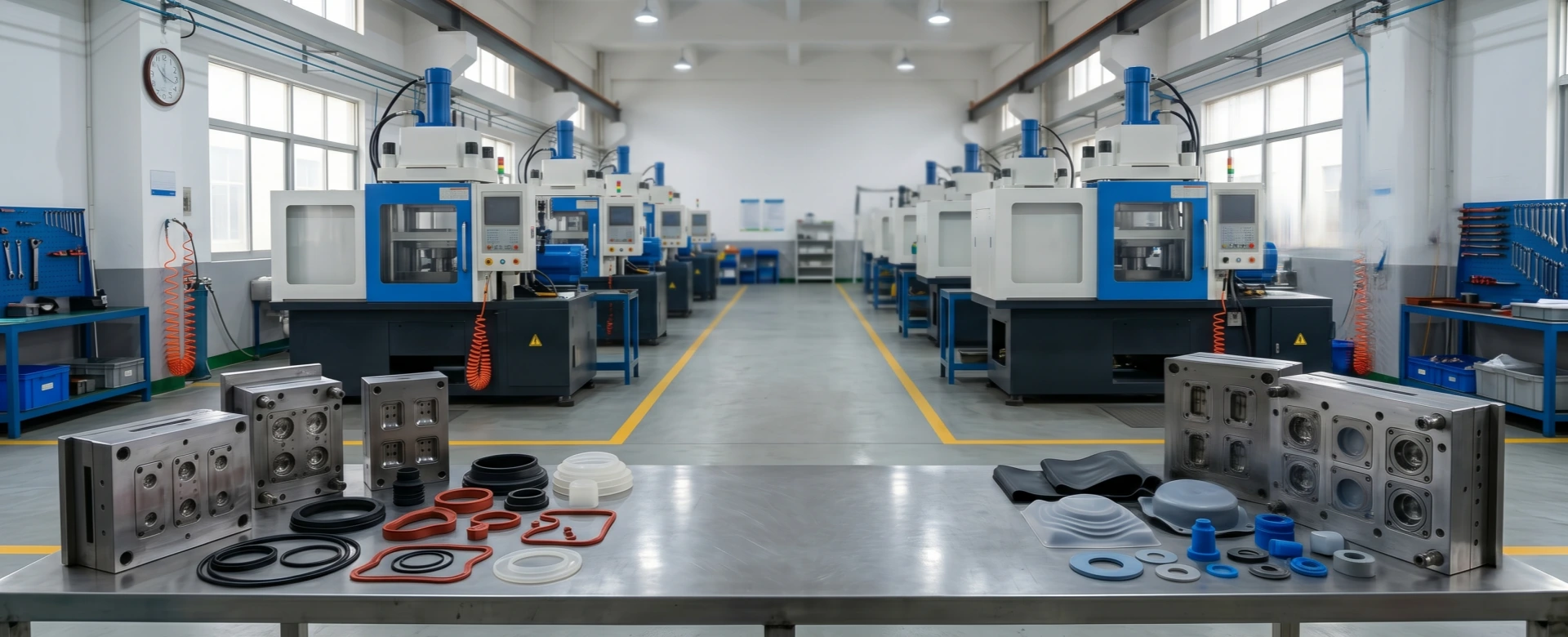
Automation and Robotic Pick-and-Place Solutions in High-Volume LSR Injection Demolding
In high-volume B2B Liquid Silicone Rubber (LSR) injection molding, production efficiency is often limited by the final demolding phase. While modern injection presses can cure parts in short cycles using cold runner systems, removing soft elastomeric parts from hot mold cavities remains a challenge. Standard thermoplastics shrink as they cool, releasing easily from mold cavities. Silicone rubber, however, expands thermally within the hot tooling ($170^{\circ}C$ to $200^{\circ}C$) and develops static adhesion against ground steel surfaces.
Relying on manual labor for part stripping slows cycle times, increases labor costs, and introduces contamination risks from human skin and airborne particles. This approach is unsuited for medical-grade or precision electronic components. Implementing high-speed, multi-axis robotic pick-and-place lines combined with custom End-of-Arm Tooling (EOAT) resolves these manufacturing constraints. This technical report provides an overview of automated LSR demolding mechanics, machine-vision verification, and Overall Equipment Effectiveness (OEE) optimization for procurement and operations teams.
1. Rheological Friction & Physical Adhesion Challenges in Silicone Extraction
Automating LSR demolding requires managing specific material properties that differentiate elastomers from rigid plastics. Due to its flexible siloxane backbone, cured liquid silicone features a low durometer and high elongation capability. Attempting to pull an intricate component out of a deep mold cavity using a basic mechanical gripper can deform the part beyond its elastic limit, causing tears along thin walls or internal seals.
Furthermore, hot, clean silicone develops a high coefficient of friction against smooth steel cavity walls. This physical cling is intensified by vacuum suction within unvented mold pockets and electrostatic charges generated during high-speed material injection. To mitigate these adhesion forces without damaging components, factories integrate mechanical ejector pin arrays, localized air-blast channels, and robotic pick-and-place systems to distribute extraction forces evenly across the part geometry.
2. Robotic End-of-Arm Tooling (EOAT) Architectural Layouts
The core of an automated LSR injection workcell is the End-of-Arm Tooling (EOAT). The EOAT must interface reliably with flexible elastomeric components at high temperatures without marking cosmetic surfaces. Industrial workcells leverage three primary gripper configurations:
- Soft-Touch Silicone Vacuum Grippers: These systems utilize custom-molded, high-temperature silicone suction cups to conform to curved or irregular part profiles. By pulling a controlled vacuum, the EOAT secures the part across a broad surface area, distributing the extraction stress to prevent localized tearing.
- Pneumatic Micro-Needle Arrays: For dense, complex parts like automotive wire-harness grommets where vacuum cups cannot establish a seal, the EOAT deploys angled micro-needles. These needles enter non-functional areas of the silicone matrix to lift the part, retracting automatically once the part reaches the collection container.
- Non-Marring Carbon Fiber Part-Strips: To minimize weight and maximize robot acceleration, gripper frames are machined from high-tensile carbon fiber. They incorporate integrated air-manifold channels that direct micro-bursts of ionized compressed air behind the part, breaking the static vacuum bond between the silicone and the mold steel.
3. Optical Sensor Integrations & Machine Vision Cycle Verification
Automating part extraction introduces operational risks if a component tears or fails to release from the mold cavity. If the injection press closes a subsequent cycle onto a retained silicone part, the clamping force can compress the material beyond its limits, potentially causing permanent structural damage to high-polished steel cavities or cold runner nozzle tips.
To prevent double-molding tool damage, automation lines utilize integrated high-resolution machine vision systems. Immediately following robotic EOAT retraction, a high-speed camera array captures an image of both mold faces. The vision software performs a real-time pixel grid comparison against a baseline image of an empty mold. If the system detects a retained part, a flash line error, or unremoved scrap material, the control system pauses operation, sounds an alarm, and stops the press from closing until an operator clears the tool face.
4. Manufacturing Performance & Operations Comparison Matrix
Analyzing production metrics demonstrates the operational impact of migrating from traditional manual stripping methods to fully automated robotic injection cells.
Manual Extraction vs. Automated Robotic Demolding
| Operational Variable | Manual Scrap-Stripping Operations | Linear Pneumatic Pick Robots | 6-Axis Vision-Guided Automation |
|---|---|---|---|
| Extraction Speed | Slow (12 – 25 Sec / cycle) | Moderate (5 – 8 Seconds) | Ultra-Fast (2.5 – 4.0 Seconds) |
| Cosmetic Damage Risk | High (Human tool marring) | Low (Linear path restrictions) | Near Zero (Controlled EOAT) |
| Tool Protection Security | Reliant on operator attention | Blind operation (No check) | 100% Machine Vision Verified |
| Overall Equipment OEE | Low / Fluctuating (65% – 72%) | Stable (82% – 85%) | Maximized Optimization (92% – 96%) |
5. DFM and Sourcing Framework for Automated LSR Systems
To leverage automated demolding effectively, product engineering and procurement teams should incorporate key automation considerations into their initial project plans:
- Incorporate Robotic Pickup Pads in CAD Layouts: Gasket blueprints should feature an unribbed, flat surface area measuring at least $5.0\text{ mm}\times5.0\text{ mm}$. This provides a reliable pickup zone for robotic vacuum cups to secure a seal during high-speed extraction.
- Verify Ejector Pin Placement: Mechanical ejector pins should align with functional pickup nodes on the robotic arm, pushing the component upward into the vacuum cups simultaneously to minimize material stretching.
- Require Part-Retention Control in Molds: Tool designs must specify intentional texturing differences or undercuts between the mold halves. This ensures components remain on the moving side of the mold upon opening, positioning them correctly for the robotic path.
Maximize Production Throughput with Reemane’s Automated LSR Injection Cells
Eliminate manual cycle latency variation, lower per-piece production costs, and maintain particulate-free material tracking across high-volume medical and automotive production runs. Reemane provides full inline 6-axis robot programming, customized end-of-arm-tooling development, and integrated machine-vision cavity monitoring safety systems.